- Determining output attenuation of modulator before being distributed to the customers.
- Determining amount of attenuation along the channel.
- Knowing the strengthening of the cable television amplifier.
1 Spectrum Analyzer
1 3 Channel Modulator
 | ||||
2 Connectors of Matching Impedance 75 ohm
1 Television
1 Connecting Cable 75 ohm (+/- 2 m)
1 Coaxial Cable RG-59 75 ohm (+/- 140 m)
1 Connecting Cable 75 ohm (+/- 2 m)
1 Coaxial Cable RG-59 75 ohm (+/- 140 m)

1 N male to BNC female Connector
1 Amplifier

1 Splitter

C. CIRCUIT DIAGRAM

D. BASIC THEORY
Head End
End provides event signals (programs) for all of channels. Local and faraway broadcasting were captured by an antenna mounted on the top of very high tower in order to extend the limit distance of view. These signals can be distributed as their home channel number or be heterodyned into different channel frequencies.
Cable television headend is a master facility for receiving television signals for processing and distribution over a cable television system. The headend facility is normally unstaffed and surrounded by some type of security fencing and is typically a building or large shed housing electronic equipment used to receive and re-transmit video over the local cable infrastructure. One can also find head ends in power line communication (PLC) substations and Internet communications networks.
Reception
The cable TV headend will normally have several large C-Band FSS-type television receive-only satellite television dishes for reception of cable/satellite TV networks. A dedicated, non-movable dish is required for each satellite that the cable TV utility wishes to receive cable channels from for distribution over its system. For reception of signals from several adjacent satellites, a larger non-parabolic multi-satellite dish (such as the Simulsat) that can see up to 3 or more satellites is often used. Many digital cable systems use services like HITS ("Headend in the Sky"), a unit of Comcast, which carry hundreds of channels on just a few satellites; this is commonly used by small systems to expand service without adding expensive new dishes or other equipment
Most cable TV systems also carry local over-the-air television networks for distribution. Since each terrestrial channel represents a defined frequency, a dedicated commercial-grade receiving antenna is needed for each channel that the cable company wishes to receive and distribute. Smaller systems may use a broadband antenna to share several channels. These antenna are often built into a single tower structure called a master antenna television structure. Commercial TV pre-amplifiers strengthen the weakened terrestrial TV signals for distribution.
Some cable TV systems receive the local television stations' programming by dedicated coaxial, microwave link or fiber-optic line, installed between the local station and the headend. A device called a modulator at the local station's facilities feed their programming over this line to the cable TV headend, which in turn receives it with another device called a demodulator. It is then distributed through the cable TV headend to subscribers. This is usually more reliable than receiving the local stations' broadcasts over the air with an antenna. However, off-air reception is used as a backup by the headend in case of failure. In some cases systems receive local channels by satellite.
Other sources of programming include those delivered via fiber optics, telephone wires, the Internet, microwave towers and local community access channels that are sent to the cable headend on an upstream frequency over the cable system itself (known in the industry as "T"-channels), or via a dedicated line set up by the cable company, as mentioned earlier for reception of local television stations' programming by the headend.
Signal processing
Once a television signal is received, it must be processed. For digital satellite TV signals, a dedicated commercial satellite receiver such as a GI DSR4400X or a Scientific Atlanta/PowerVu satellite receiver is needed for each channel that is to be distributed by the cable system; these are usually rack-mountable receivers that are designed to take up less space than consumer receivers. They output Video and stereo audio signals as well as a digital signal for digital plants.
Analog terrestrial TV signals require a processor which is a RF receiver that outputs Video and Audio. In some cases the processor will include a built-in modulator.
Digital terrestrial TV signals require a special digital processor.
Digital channels are usually received on an L band QAM stream from a satellite, which uses multiplexing. Using special receivers such as the Motorola MPS, the signal can be demultiplexed or "Demuxed" to extract specific channels from the multiplexed signal. At this point, local insertion may be performed to add content specifically targeted to the local geographic area.
Modulation
Cable television signals are then mixed in accordance with the cable system's channel numbering scheme using a series of cable modulators (one for each channel), which is in turn fed into a frequency multiplexer or signal combiner. The mixed signals are them sent into a broadband amplifier and then sent into the cable system by the trunk line and continuously re-amplified as needed.
Modulators essentially take an input signal and attach it to a specific frequency. For example in North America, NTSC standards dictate that CH2 is a 6 MHz wide channel with its luminance carrier at 55.25 MHz, so the modulator for channel 2 will impose the appropriate input signal on to the 55.25 MHz frequency to be received by any TV tuned to Channel 2.
Digital channels are modulated as well; however, instead of each channel being modulated on to a specific frequency, multiple digital channels are modulated on to one specific NTSC frequency. Using QAM (Quadrature Amplitude Modulation), a CATV operator can place usually up to eight channels on one specific frequency so channel 2 may actually be carrying channels 2-10 in your city. STBs (Set top boxes) or CableCards are required to receive these digital signals and are provided by the cable operator themselves.
Cables Distribution
The losses frequency in coaxial cables are high, especially those are working in the super frequency from cable TV. However, the losses of channel were offset by using a radio frequency amplifier (RF amplifier) with a wide field of frequency placed along the cable network as shown in Figure 2.3.
Main channel of the distribution systems is trunk. From this main line, the branch cables were extended to the groups of customers. Channel for each customer is called drop.
Each trunk channel amplifier has same strengthening with channel loss for the distance between amplifier. Its typical value is 40 dB, or strengthening of the voltage is 100.
The plant normally consists of trunk lines that run from one distribution amplifier to the next. Feed lines run from a bridge amplifier inside the distribution amplifier to the drops that are placed in front of each house. From the drop a coax runs to each home. Unused taps on the drop are normally terminated with anti-theft terminators. To extend the feed lines even further line extenders are used which are small amplifiers. Some small systems have been built without trunk lines using only line extenders every few hundred feet.
Block diagram ‘distribution system of cable television’

E. EXPERIMENTAL PROCEDURE
Before doing the test, calibration must be done first to the Spectrum Analyzer. After that, the test of output modulator can be started.
Note: For each test, before being connected to the Spectrum Analyzer will be better if using matching impedance from 75 ohm to 50 ohm (attenuation 7,8 dB).
For measurement of each TP, do not connect the entire system that will be measured. For example, only the modulator installed at the measurements of TP1, only modulator and roll cable in TP2, and so on.
1. Measure and draw frequency spectrum at the measurement point (TP1) to see the output signal level of modulator on each channel. In this test, using coaxial cable 75ohm (±2 m) with block diagram shown as below :


4. Repeat for TP 2 and TP 4 with moving the cable roll.
F. RESULT
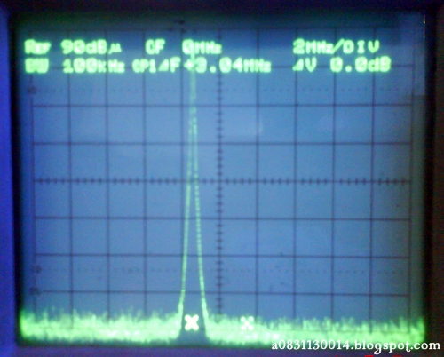
Reference Frequency


REF 90 dBμ CF 467 Mhz 2 Mhz/DIV
BW 100 Khz CP1 ΔF+2.96 Mhz ΔV -14.8 dB
TP 2
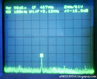
REF 90 dBμ CF 467 Mhz 2 Mhz/DIV
BW 100 Khz CP1 ΔF+3.12 Mhz ΔV -16.0 dB
TP 3

REF 90 dBμ CF 466 Mhz 2 Mhz/DIV
BW 100 Khz CP1 ΔF+3.52 Mhz ΔV -38.8 dB
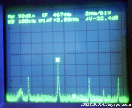
TP 4

REF 90 dBμ CF 467 Mhz 2 Mhz/DIV
BW 100 Khz CP1 ΔF+2.80 Mhz ΔV -32.4 dB
TP 5, 6, 7

REF 90 dBμ CF 499 Mhz 2 Mhz/DIV
BW 100 Khz CP1 ΔF+2.80 Mhz ΔV -28.0 dB
G. DATA ANALYSIS
Coaxial cable used in cable distribution system for cable wrapping and taking minimize radiation interference signal. Impedance which is owned by an infinite length of cable is Z0. End of channel in Zo generates maximum power transfer to the load. In the cable each of channel does not have standing waves and reflections. Zo standard in television is 75 ohm. In this experiment, the output of the modulation that enter through the coaxial cable will slowdown, then amplified by an amplifier. After that, it channeled back into the coaxial cable so that its output is not too much because it was collaborated with attenuation amplifier. Output of the coaxial cable inserted into the power splitter used by some televisions. But in practice no part of attenuation obtained because of limited tools and measuring devices are also damaged.
H. CONCLUSION
1. Output of the coaxial cable will be attenuated
2. Attenuation due to cable amplified using the amplifier
3. To use only one channel for some televisions using power splitter

2. Repeat the test using a long cable (+/- 150 m) at TP2, with block diagram shown as below. Draw the frequency spectrum and determine its level. How many attenuation dB that occurred on the cable.

3. Repeat testing for TP3, TP4, TP5, TP6, and TP7 as in steps 1 and 2.
Determine the strengthening of amplifier, cable attenuation, attenuation at splitter in each port.4. Repeat for TP 2 and TP 4 with moving the cable roll.
F. RESULT
Reference Frequency


REF 90 dBμ CF 0 Mhz 2 Mhz/DIV
BW 100 Khz CP1 ΔF+0.08 Mhz ΔV 0.0 dB TP 1

BW 100 Khz CP1 ΔF+2.96 Mhz ΔV -14.8 dB
TP 2

REF 90 dBμ CF 467 Mhz 2 Mhz/DIV
BW 100 Khz CP1 ΔF+3.12 Mhz ΔV -16.0 dB
TP 3

REF 90 dBμ CF 466 Mhz 2 Mhz/DIV
BW 100 Khz CP1 ΔF+3.52 Mhz ΔV -38.8 dB
TP 4
REF 90 dBμ CF 467 Mhz 2 Mhz/DIV
BW 100 Khz CP1 ΔF+2.80 Mhz ΔV -32.4 dB
TP 5, 6, 7

REF 90 dBμ CF 499 Mhz 2 Mhz/DIV
BW 100 Khz CP1 ΔF+2.80 Mhz ΔV -28.0 dB
G. DATA ANALYSIS
Coaxial cable used in cable distribution system for cable wrapping and taking minimize radiation interference signal. Impedance which is owned by an infinite length of cable is Z0. End of channel in Zo generates maximum power transfer to the load. In the cable each of channel does not have standing waves and reflections. Zo standard in television is 75 ohm. In this experiment, the output of the modulation that enter through the coaxial cable will slowdown, then amplified by an amplifier. After that, it channeled back into the coaxial cable so that its output is not too much because it was collaborated with attenuation amplifier. Output of the coaxial cable inserted into the power splitter used by some televisions. But in practice no part of attenuation obtained because of limited tools and measuring devices are also damaged.
H. CONCLUSION
1. Output of the coaxial cable will be attenuated
2. Attenuation due to cable amplified using the amplifier
3. To use only one channel for some televisions using power splitter
No comments:
Post a Comment